

Automated Edge Inspection
Edges may look insignificant in a set of technical drawings. In reality, they determine everything: whether a component can be assembled, whether it can be handled safely, how forces are transmitted during operation and how it behaves over its service life under load.
An edge that remains too sharp can cause injuries and create stress concentrations. An edge with nonconforming chipping can lead to leaks, noise and premature wear. NELA’s automated edge inspection detects and evaluates edges during ongoing production. Every component, 100%, in cycle time.
Edge inspection is performed optically, contact-free and objectively – with an evaluation that accurately inspects the specified edge break (chamfer) while reliably detecting actual edge chipping. This gives you a robust inspection basis, reduces complaints and ensures lasting quality assurance in your production.
Edge break, edge chipping, burrs: Why the distinction is crucial
In manufacturing practice, the term “edge break” is used with two very different meanings – and in a reliable inspection process, both must be clearly distinguished from one another.
-
Edge break as a drawing specification
An edge break in the design sense is the intentional breaking of a sharp edge. Drawings often specify “break edge 0.3 × 45°”, “R0.2” or include a general note according to DIN EN ISO 13715. The objective is a defined chamfer or radius that prevents the edge from causing injuries during handling, interfering with assembly or becoming the starting point for stress cracks during operation. The inspection task here is: Is the chamfer or radius present in the specified geometry? Does it have the required width, depth and angle? And is it executed uniformly all the way around?
-
Edge chipping as a defect pattern
Edge chipping is the opposite: an unintended, locally limited loss of material at a component edge. The causes are varied – impact marks during handling, unfavorable tool kinematics during grinding, brittle material behavior during deburring, edge zone breakouts in sintered and ceramic components, chipping on punched cut edges or spalling on hardened materials. The inspection task here is: Are there any chips? How large are they, where are they located, and do they exceed the permissible tolerance?
-
Burrs and sharp edges
Burrs are the counterpart to edge breaks: protruding, unremoved material that remains on the edge after the machining process. They can cause functional issues, such as damage to seals or assembly problems, and represent a safety risk in many applications. Inspection must therefore work in three directions at once: evaluating the target geometry of the edge break, detecting unwanted chipping and reliably identifying burrs.
For engineers: DIN EN ISO 13715:2020 (based on ISO 13715:2017) specifies the indication and dimensioning of edges of undefined shape in technical product documentation. It distinguishes between external edges, which may have a burr, material removal or a zero condition, and internal edges, which may have a passing or material removal. The drawing indication is made using an edge symbol with a sign: “+” permits material excess (a burr on external edges or a passing on internal edges), while “–” permits material removal. The standard specifies typical value steps between ±0.02 mm and ±2.5 mm, depending on the function and component. For non-dimensioned edges, the general specification “external edge −0.2 mm / internal edge +0.4 mm” is frequently used in accordance with the technical delivery conditions of the German Turned Parts Industry Association. Without a clear drawing indication, the general note “edges broken, sharp edges not permitted” is often used – a note that requires interpretation in practice and must be translated into measurable limit values for automated inspection.
Why edges are so critical
Edges are the interface between surface and surface, between component and environment, between functionality and functional failure. Mechanical stresses concentrate at edges, cracks start there, seals can catch there, and residues from cleaning and handling can accumulate there. Any deviation from the specified condition therefore has a disproportionately strong impact on the function of the entire component.
A sharp-edged bearing ring can damage a sealing lip during assembly. An insufficiently edge-broken tooth root on a gear creates a notch effect. Chipping on the thread flank of a fastener leads to uneven load distribution and possible thread stripping when tightening torque is applied. Edge chipping on a sintered indexable insert can cause the tool to break during the next machining operation. In all cases, the defect is only a few micrometers in size – but its consequences are costly.
For manufacturers, this means: Anyone who fails to inspect edge quality reliably risks assembly errors, complaints and safety incidents. Especially in safety-critical components (automotive supply industry, medical technology, hydraulics), edge inspection is no longer optional. It is an integral part of every approval process.
Conventional edge inspection methods and their limitations
Visual inspection, optical comparators, edge probes, profilometers: proven methods, but rarely suitable for series production.
Several methods have become established for inspecting edge breaks and edge chipping.
The common problem: All conventional methods are designed for sample inspection, manual evaluation or laboratory metrology. For 100% inspection of edge geometry and edge quality in cycle time – simultaneously, on all edges of a component, without an additional handling step – they are either too slow, too selective or too one-dimensional.
Manual visual inspection with a magnifying glass
The inspector places the component under an illuminated magnifier or stereo microscope, rotates it under different lighting angles and assesses whether chipping, burrs or insufficient edge breaks are present. Fast, flexible and requiring no programming effort.
Disadvantages in series production:
- Subjective: two inspectors, two assessments, varying levels of concentration throughout the shift
- No measurable values, only assessments such as “OK” or “not OK”
- Hardly any clearly traceable documentation, no traceability for individual parts
- No longer economically viable for batch sizes > 1,000 parts per shift
- Small edge breaks < 0.1 mm can no longer be reliably detected, even with a magnifying glass
Optical comparators and edge probes on coordinate measuring machines
An optical comparator displays the edge at high magnification on a screen, and the edge dimensions are measured manually or semi-automatically. On a coordinate measuring machine, a tactile or optical edge probe captures the geometry at individual points. The results are considered a reference.
Limitations of the method:
- Slow: measurement of each edge takes seconds to minutes
- Point-by-point measurement; chipping between measuring points remains undetected
- Extensive programming and setup required for each component variant
- Only economical for sample inspection, no 100% coverage
- Requires metrology room conditions: temperature, vibration, cleanliness
Did you know? With tactile edge probes, the probe ball diameter causes a systematic rounding effect: a 2 mm probe ball cannot accurately trace an edge with a radius < 1 mm due to its geometry. The result is edges that appear “rounder” than they actually are. This is why optical and tactile edge measurements can produce different values on the same component.
Contour measuring instruments and profilometers
A high-precision probing system traces a defined profile across the edge and provides an exact 2D contour profile. From this, edge break width, depth and angle are calculated. Indispensable for standards-compliant edge measurement in the laboratory.
Limitations of the method:
- Tactile: sensitive or coated surfaces may be scratched
- Only one measuring track per measurement; circumferential inspection requires many individual measurements
- The component must be precisely aligned and securely clamped
- Too slow for inline inspection in second-by-second cycle times
- No area image, no information about chipping next to the measuring track
Conventional 2D image processing
Simple camera systems can capture edge contours as silhouettes and compare them with a target geometry. This works reliably for edge inspection in transmitted light, for example with stamped parts against a bright-field background.
Limitations of the method:
- Only the silhouette can be captured, no information on edge break depth or chamfer
- Reflective metal edges create reflections that are difficult to interpret
- Chipping “in depth” (not in the projection direction) is not detected
- No 3D information, and therefore no reliable geometric measurement of the chamfer
- Color features are often mistaken for defects, resulting in a high false reject rate
Our approach: optical edge inspection
Measure every edge. Find every chip.
NELA’s automated edge break inspection combines two tasks in a single optical inspection process: it measures the specified edge break, i.e. the chamfer or radius according to the drawing, while simultaneously detecting unwanted edge chipping, burrs and damage along the same edge.
This is made possible by the interaction of several technologies: telecentric image acquisition for precise measurement of the edge contour, shape-from-shading, dark-field illumination for detecting even the smallest chips, and special internal and external sensors for hard-to-access edges in bores, grooves and threads. Illumination, sensor technology and evaluation software work together as a coordinated system.
The result is full-perimeter, gap-free edge inspection that can measure the edge break while simultaneously evaluating whether the edge is free from chipping, burrs and spalling. Every part is evaluated according to the same criteria. Shift after shift, batch after batch, with full documentation.
The physics behind edge inspection: how light reveals geometry
A perfect edge reflects light at a clearly defined angle. An edge break creates two reflection areas positioned at an intermediate angle. A sharp edge produces a narrow, intense reflection line. And a chip generates scattered light in all directions: irregular, chaotic and clearly deviating from the target condition. The key is to use exactly the right illumination for each of these inspection tasks in order to maximize contrast.
Telecentric optics: measuring edges without perspective error
Telecentric lenses view all points within the measurement field with parallel chief rays. This means that an edge is always represented at the same image scale, regardless of whether it is closer to or farther away from the camera. This is crucial for measuring chamfers, radii and edge distances. Conventional lenses would image the edge at different sizes depending on its position, thereby distorting the measurement. In combination with high-resolution camera sensors and transmitted-light illumination, edge dimensions can be determined with a repeatability of ± 1 µm or better.
Shape-from-shading: the third dimension of the edge
A silhouette alone shows where the edge runs, but not how it continues inward. Shape-from-shading closes this gap. In the multi-image variant used here, the method is also technically referred to as photometric stereo: the inspection object is illuminated sequentially from several precisely defined directions, with one image captured for each illumination condition. An algorithm uses the varying shadow gradients to determine the surface normals of the area for each pixel and derive a fine three-dimensional height relief of the edge from them.
Dark-field illumination: chipping in bright contrast
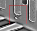
For the defect detection side of edge inspection, dark-field illumination is the key technology. Low-angle grazing light is reflected past the camera by an intact surface: the image remains dark. As soon as a chip, breakout or damage is present in the light path, however, light is scattered toward the camera. The defect appears bright against a black background, with high contrast, even at dimensions in the micrometer range.
This allows the typical appearances of edge chipping to be detected reliably: chipped edges on sintered parts, spalling on hardened raceways, edge breakouts on punched cut edges, impact marks from handling and small irregularities on thread flanks.
Dome illumination: detecting accompanying effects
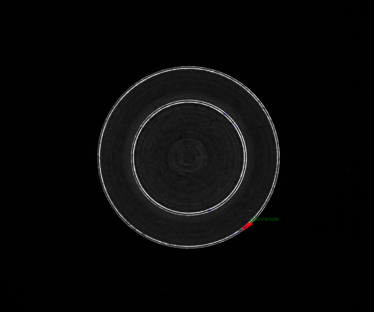
Edge chipping rarely occurs in isolation. It is often accompanied by discoloration, microcracks or raised material resulting from the machining process. Dome illumination provides diffuse light from many directions, eliminates directional reflections and makes material-related surface changes around the edge visible. This expands the diagnostic scope: not only the chip itself, but also the context in which it occurred can be documented – valuable information for root cause analysis and process optimization.
Specialized sensors for internal and external edges
Not every edge is openly accessible. In practice, it is often internal edges in particular that determine component quality: the upper edge of a bore, the flank of an internal thread, the transition of a blind-hole countersink, the internal chamfer of a through hole. For these cases, NELA uses dedicated specialized sensors – for example INside sensors for bores and internal contours, OUTside sensors for cylindrical surfaces and external edges, as well as TOPside and BOTTOMside sensors for edges on end faces. This makes edge inspection fully circumferential: every edge of a component, from all sides, in a single pass.
When optics reach their limits: hybrid inspection concepts
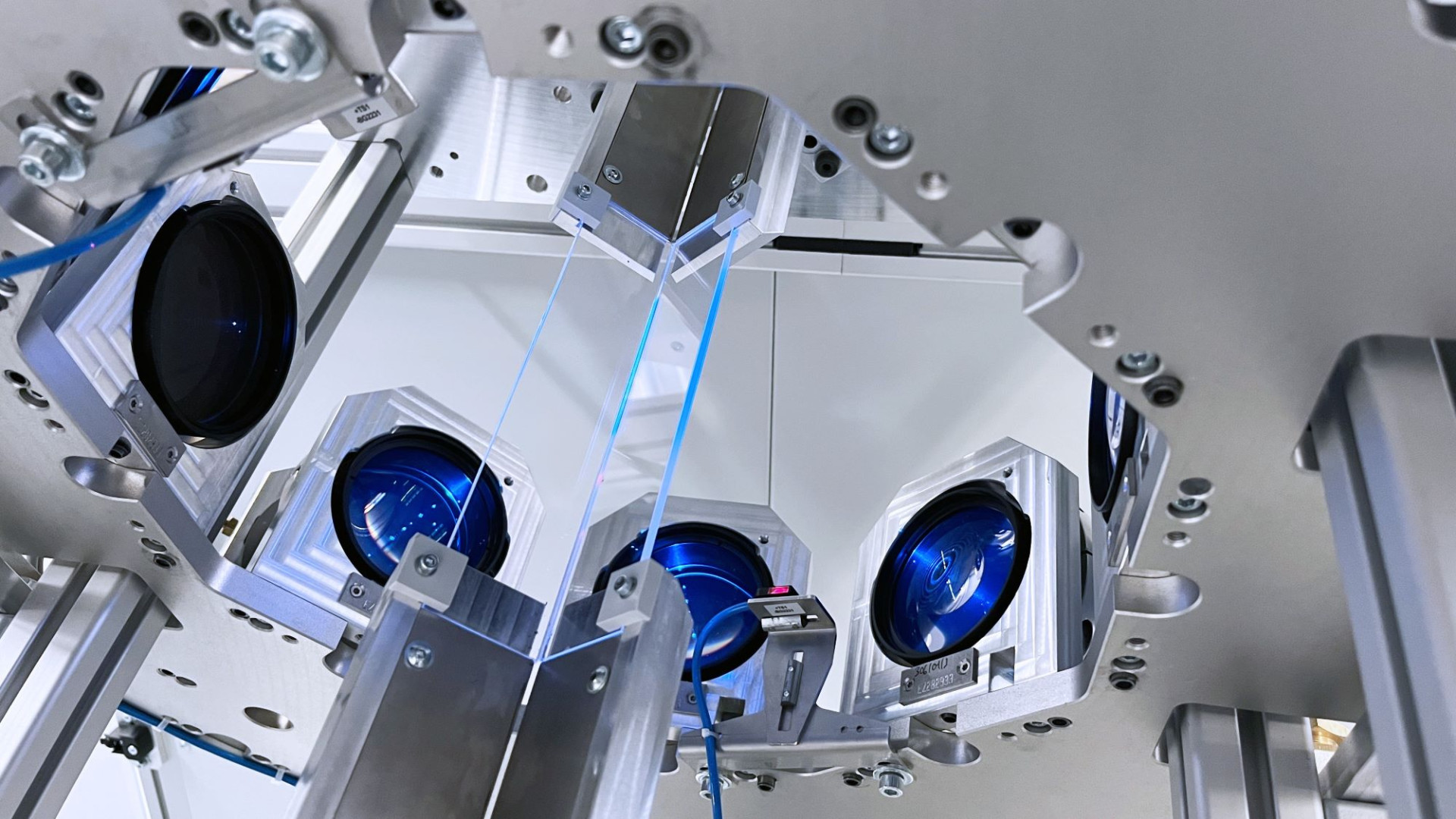
Optics where they excel. Tactile reference measurement where standards require it. Optical edge inspection provides area-based data at high resolution and speed. In certain applications, however, standards or customer inspection plans require reference dimensions determined by tactile measurement. For example, for the documented approval of a machined chamfer on safety-critical components. For such cases, NELA combines optical inspection with complementary tactile metrology within the same system.
The advantage of integration: The component passes through both methods within the same cycle time. Optical inspection checks every single edge across the entire area and also detects chipping between the tactile measuring points. The complementary tactile measurement provides the standards-required reference value at defined positions. Both results are brought together in the NELA VisionCheck software and evaluated jointly for the OK/NOK decision.
Did you know? For a reliable correlation between optical and tactile edge break measurements, alignment of the evaluation parameters is crucial: Where does the chamfer begin, where does it end, and which reference system is used for the measurement? NELA coordinates this together with the customer on the basis of reference parts with known measurement values. The result is an optical inspection process whose values match the laboratory reference.
Measuring edges with NELA
Up to 100,000 parts per hour. Measuring accuracy from ± 1 µm.
NELA systems are built for series production. On glass table systems such as TAVI.01, TAVI.01-XL and the dual-table system TAVI.02, end-face edges, lateral edges and internal edges are inspected in a single pass. Fully automated, inline and in cycle time. For cylindrical and elongated serial parts, glass slide inspection systems such as SKIVI are available; for complex component geometries or particularly demanding inspection points, the indexed ROVI systems provide targeted positioning and multiple viewing angles.
Edge inspection uses NELA’s full sensor portfolio: DIMension or HEIGHT for the transmitted-light silhouette and edge measurement, TOPside and BOTTOMside for end-face edges including internal and external chamfers, OUTside for lateral and external edges, and INside for bores and internal threads. The illumination can be parameterized on several levels and adapted to the respective material and edge geometry.
Typical defects detected during edge inspection
- Edge chipping on sintered parts, sintered magnets and ceramic components
- Spalling on hardened raceways and rolling bearing components
- Punching breakouts and edge tearing on fineblanked and formed parts
- Burrs and protruding material after machining, punching or forming
- Sharp edges on drawing-specified edges that have not been broken or have been insufficiently broken
- Uneven edge break along the circumference
- Impact marks and damage from transport or handling
Typical applications:
- Sintered components (cams, gears, bushings, flanges, indexable inserts)
- Precision and micro-precision turned parts with tight edge tolerances
- Fasteners (screws, bolts, nuts, rivets), including thread flanks
- Stamped and fineblanked parts with defined cut geometry
- Rolling bearing rings and hardened raceways with internal and external chamfers
- Medical technology components with high requirements for injury prevention
Inspectable part sizes range from 1 mm to approx. 120 mm outside diameter, with repeatability starting from ± 1 µm – sufficient to reliably measure edge breaks of just a few tenths of a millimeter and provide dependable proof of even tight customer tolerances. For sensitive components such as sintered or ceramic parts, particularly gentle handling concepts are used to ensure that the edge being measured is not damaged during the inspection process itself.
Typical measured edge break dimensions:
- Chamfer width and chamfer angle (e.g. 0.3 × 45°)
- Edge radius on rounded edges
- Depth and width of the edge break at the transition to the surface
- Uniformity of the edge break along the entire circumference
- Position and size of individual chips relative to the nominal contour

The software behind it: NELA VisionCheck
Every inspection result is automatically logged: with edge profile, calculated measured values, defect image, time stamp and machine ID. VisionCheck enables the creation of individual inspection programs and reduces false rejects through adaptive surface algorithms. This creates complete documentation of every single edge.
On request, NELA VisionCheck can be supplemented with a powerful AI module that makes your inspection process even more efficient and flexible.
