
Optical crack inspection
Anyone who delivers cracked components risks not only customer complaints, but also product liability claims, recalls, and reputational damage. Costs that far exceed any inspection system.
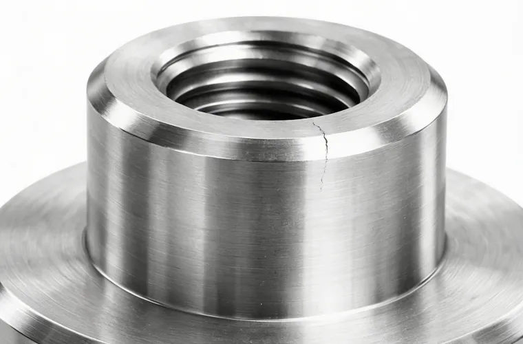
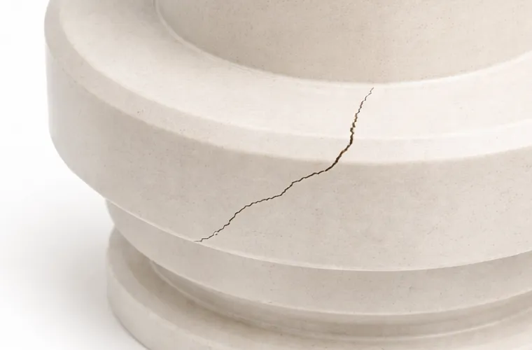
Cracks are among the most critical defect types in safety-relevant components and are often difficult to detect: hairline cracks in brake discs, structural cracks in steering components, or incipient cracks in pressure vessels. If such defects are identified too late, the consequences can be severe—technically, economically, and in terms of safety.
NELA’s automated optical crack inspection captures 100% of your components and detects even the smallest anomalies at an early stage. Inspection is fast, objective, and delivers documented results. This provides you with a reliable inspection basis, reduces the risk of failures, and ensures the long-term quality of your production.
Why cracks are so dangerous
Cracks do not necessarily result from major defects. They are often the outcome of standard manufacturing processes: forming, joining, turning, milling, hardening, and grinding. All of these processes generate localized residual stresses within the material structure. If a component cools unevenly, distortion occurs. When cyclic loads act on a material with structural inhomogeneities, an initially invisible crack can grow silently.
The critical point: Many cracks are functionally non-critical in their initial state. Only under operational loads, temperature fluctuations, or corrosion do they propagate and eventually lead to sudden failure. In safety-relevant components such as connectors, axles, steering, or braking parts, this can have severe consequences.
For engineers:
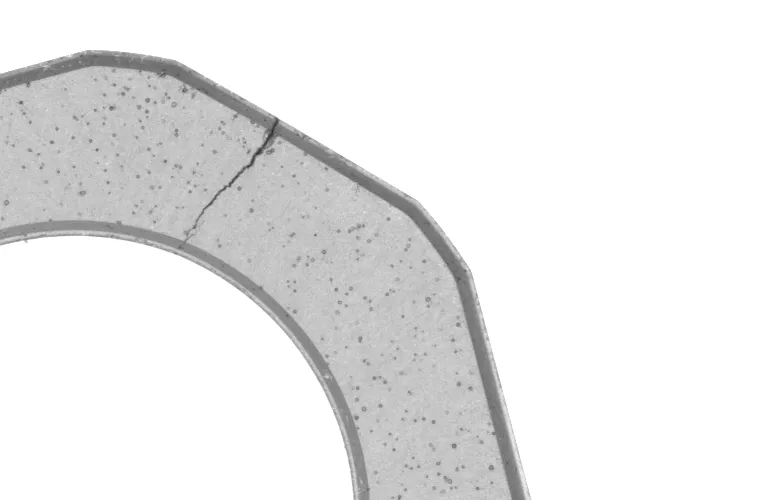
Intergranular cracks, which propagate along grain boundaries, are particularly insidious. They can be caused by heat treatment, unsuitable coolants, or incorrect cutting speeds. Under a light microscope, such structural defects often only become visible at magnifications of 50–200x, making them highly challenging to detect in serial inspection using conventional methods.
Conventional crack inspection methods and their limitations
Dye penetrant testing, eddy current testing, magnetic particle inspection: proven, but not scalable.
There are good reasons why these methods are widely used in practice. But there are equally valid reasons why they reach their limits in high-volume production. All three methods are designed for sample-based inspection or manual testing. In a production line with 50,000 to 100,000 parts per shift? Not suitable. Too slow, too subjective, too costly to integrate into the process.
Dye penetrant testing (PT – Penetrant Testing)
The principle is simple and effective: a red dye (penetrant) enters open cracks via capillary action. After intermediate cleaning and application of a white developer, defects become visible through color contrast. Due to this coloration, the method is also referred to as “red-white inspection.”
Disadvantages in high-volume production:
- Multi-stage process (pre-cleaning → penetrant → dwell time → intermediate cleaning → developer → evaluation), difficult to integrate into cycle times
- Subjective evaluation: two inspectors, two different results
- Use of chemicals and mandatory disposal requirements
- Only suitable for open surface cracks; internal defects are not detected
- No automated documentation
Did you know? The detection sensitivity of dye penetrant testing strongly depends on the viscosity of the penetrant, the dwell time, and the surface roughness. At Ra > 6.3 µm, the method quickly becomes unreliable, as the penetrant can remain trapped within the surface roughness itself, generating false indications.
Magnetic particle inspection (MT – Magnetic Testing)
Ferromagnetic components are first magnetized so that magnetic field lines pass through the material. If a crack is present, the field lines can no longer continue undisturbed and instead emerge at the surface, creating what is known as a leakage field. Magnetic particles applied to the surface accumulate in this leakage field, making the crack visible. This effect is particularly pronounced when using fluorescent testing media, which glow under UV light and make even fine cracks clearly detectable.
Disadvantages:
- Only suitable for ferromagnetic materials (no aluminum, no stainless steel, no ceramics)
- Components must be demagnetized after inspection
- Requires a UV light source and a dark inspection environment
- Difficult to automate for complex geometries
- Also subjective and not suitable for inline inspection
Eddy current testing (ECT)
An alternating electromagnetic field induces so-called eddy currents in electrically conductive components. If the current flows undisturbed, the electrical resistance remains uniform. However, if surface cracks are present, the current flow is disrupted at these locations. This leads to a change in impedance, i.e., the AC resistance, which can be measured. The method is highly precise and fast and is particularly well suited for rotationally symmetrical components, as it can be easily automated.
Limitations of the method:
- Only works with electrically conductive materials
- Limited penetration depth: in the kHz range often only a few millimeters, meaning near-surface defects can be detected, while deeper cracks may remain undetected
- For complex geometries: liftoff effects caused by varying distances between the sensor and the component can distort the signal
- Limited reliability in the presence of material inhomogeneities (pores, inclusions)
Did you know? In eddy current testing, frequency determines how deeply the eddy currents penetrate the component: high frequencies for near-surface defects, low frequencies for deeper defects, albeit with reduced sensitivity for small cracks.
Our approach: Optical inspection as the leading method
See cracks as they truly are.
-
 1
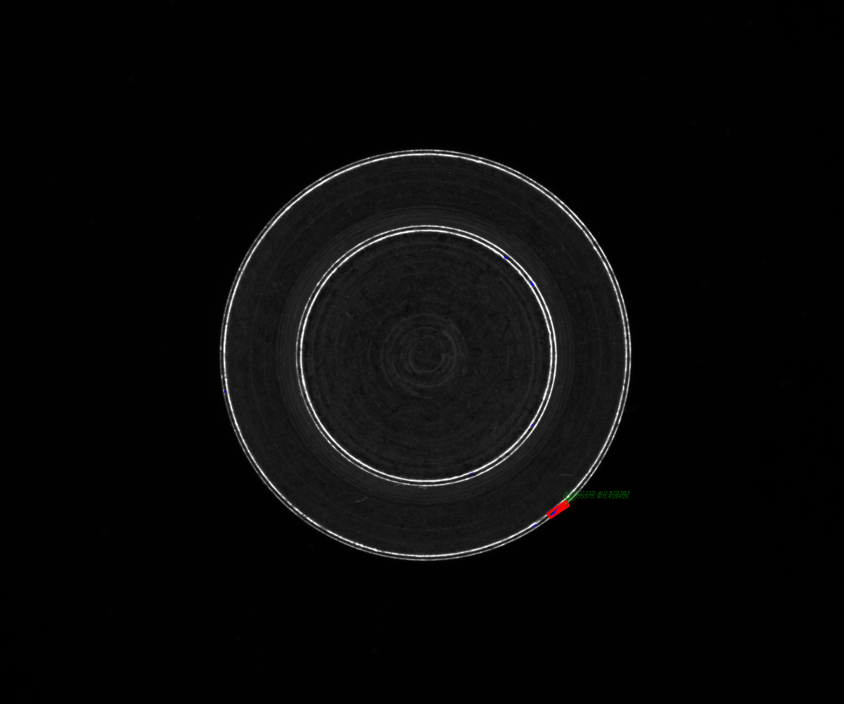
1NELA’s automated optical crack inspection detects cracks by making even the smallest surface irregularities visible and analyzable using advanced illumination and camera sensor technology. Cracks, pores, or incipient cracks alter the way light is reflected—these deviations are precisely what the camera and software reliably detect.
-
 2
2Illumination, camera, and evaluation software work together as a coordinated system. This ensures that every area of the surface is inspected and automatically assessed in the shortest possible time. The inspection is contactless, requires no chemicals, and eliminates additional process steps such as cleaning or demagnetization. At the same time, subjective human evaluation is no longer required.
-
 3
3The result is a reliable crack inspection with clear, reproducible results: 100% of all parts are inspected, anomalies are reliably detected, and inspection results are fully documented. This ensures confidence in quality assurance and provides a solid basis for traceability, audits, and complaint management.
The physics behind crack inspection: why illumination is everything
A crack itself does not generate a signal. What makes it visible is the right light, at the right time, from the right angle.
Dark-field illumination
In dark-field illumination, light strikes the surface at a very shallow (grazing) angle. According to the principle of angle of incidence = angle of reflection, a smooth surface reflects the light completely away from the camera. The image remains dark. However, if a depression, scratch, or crack is present in the illuminated area, light is scattered toward the camera. The defect appears bright against a dark background.
Result: Cracks, grooves, and impact marks become highly visible with strong contrast, even when they are only a few micrometers deep.
Did you know? The illumination angle in dark-field typically ranges from 5–15° relative to the surface. For cracks with a width below 10 µm and a depth below 5 µm, the achievable contrast strongly depends on the coherence length of the light source. NELA combines high-performance LEDs with defined emission angles to ensure reproducible illumination conditions, even on reflective metal surfaces.
Shape-from-Shading
In addition to conventional methods, we utilize Shape-from-Shading (SFS). In this approach, the inspection object is sequentially illuminated and captured from multiple precisely defined directions. Instead of mechanically probing the surface, an algorithm analyzes the varying shadows and brightness values of the individual images to computationally reconstruct a highly accurate three-dimensional height profile.
Focus on topography: pure structure instead of optical interference
The key advantage of SFS inspection lies in the strict separation of color information and surface structure. While conventional camera systems are often affected by varying colors, prints, or complex patterns, SFS provides a clear differentiation:
- Suppression of shading effects: Colors or purely optical features are effectively eliminated. The system makes the visual appearance of the material “disappear.”
- Pure topography: The result of the analysis is the physical surface structure. Even with high-contrast patterns, depressions, scratches, or elevations are clearly extracted.
Through this spatial analysis, the software can reliably distinguish between purely optical features and actual geometric deviations. Critical defects such as cracks or voids are unambiguously identified based on their true depth. Harmless surface features or material-specific pores, which often appear as defects in 2D images, are correctly classified as non-critical.
The result: a significantly reduced error rate and maximum process stability in your quality assurance—even for components whose optical properties would challenge conventional inspection methods.
Dome illumination
Diffuse light from dome illumination is ideal for detecting rust, temper colors, or corrosion marks around cracks. It eliminates directional reflections and reveals material changes that would remain invisible under dark-field illumination.
Cracks rarely occur in isolation. They are often accompanied by effects such as discoloration due to thermal influence or corrosion along the crack edges. With our inspection methods, both can be reliably detected.
When optics alone are not enough: eddy current testing as a complement
The best of both worlds.
Optical inspection has a physical limitation: it can only detect what is visible on the surface. Defects located just below the surface or in non-visible areas may remain undetected even with optimal illumination. For applications where both surface cracks and subsurface defects must be identified, we combine optical inspection with eddy current testing.
What remains within the domain of eddy current testing?
- Very fine, closed surface cracks (< 5 µm in width)
- Subsurface cracks close to the surface (up to approx. 1–2 mm depth, depending on frequency and material)
- Applications where standards or customer specifications explicitly require ECT
For all other applications, optical inspection alone provides the superior data basis: more information, higher resolution, and a complete view of the surface.
-
The advantage of integration: The inspection object passes through the optical inspection station and the eddy current testing system within a single cycle. No retooling. No separate line. No additional handling step. While optical inspection detects visible cracks, eddy current testing—depending on component guidance—extends the inspection scope to include the detection of subsurface defects. The results from both methods are combined within the NELA VisionCheck software.
-
Did you know? When integrating eddy current sensors into optical inline systems, liftoff management is critical. NELA addresses this with component-specific calibrated sensor mounts featuring defined spacing. Measurement data from ECT and image processing are fused in VisionCheck and jointly evaluated for pass/fail decisions.
Optical crack inspection with NELA
Up to 100,000 parts per hour. Zero compromises.
NELA systems are designed for high-volume production. They inspect end faces, side surfaces, and cylindrical surfaces in a single pass. Fully automated. Inline. In cycle.
The software behind it: NELA VisionCheck. Every inspection decision is automatically documented: with image, timestamp, defect class, and machine ID. This ensures complete quality documentation that withstands audits and guarantees full traceability within the supply chain.
Typical defects detected during crack inspection:
- Hairline cracks and incipient cracks (including fine surface cracks < 0.1 mm in width)
- Grinding burn and machining cracks caused by thermal overload
- Cold forming cracks in stamped and formed parts
- Shrinkage cavities and open voids (e.g., in cast components)
- Parting line cracks and mold-related cracks in sintered components
Applications:
- Fasteners (screws, bolts, bushings)
- Automotive safety components (axle parts, braking systems, steering components)
- Sintered and cast components
- Medical technology components
- Pressure vessels and valve bodies
