

Automated shrinkage cavity detection: detect internal voids before they become a problem.
A cavity in the valve wall, shrinkage porosity in a load-bearing sintered component, a gas inclusion in the brake mount: What may appear inconspicuous at first can lead to failure under load. Often only weeks or months after delivery. At a point when traceability has already become difficult.
NELAs automated shrinkage cavity detection makes these defects visible during ongoing production. Every component, 100%, in cycle time. Inspection is performed optically, contact-free and objectively, using an evaluation process that reliably distinguishes between true shrinkage cavities and material-typical pore structures.
This provides a robust basis for inspection, reduces scrap rates and sustainably safeguards the quality of your production.
Why shrinkage cavities are so critical
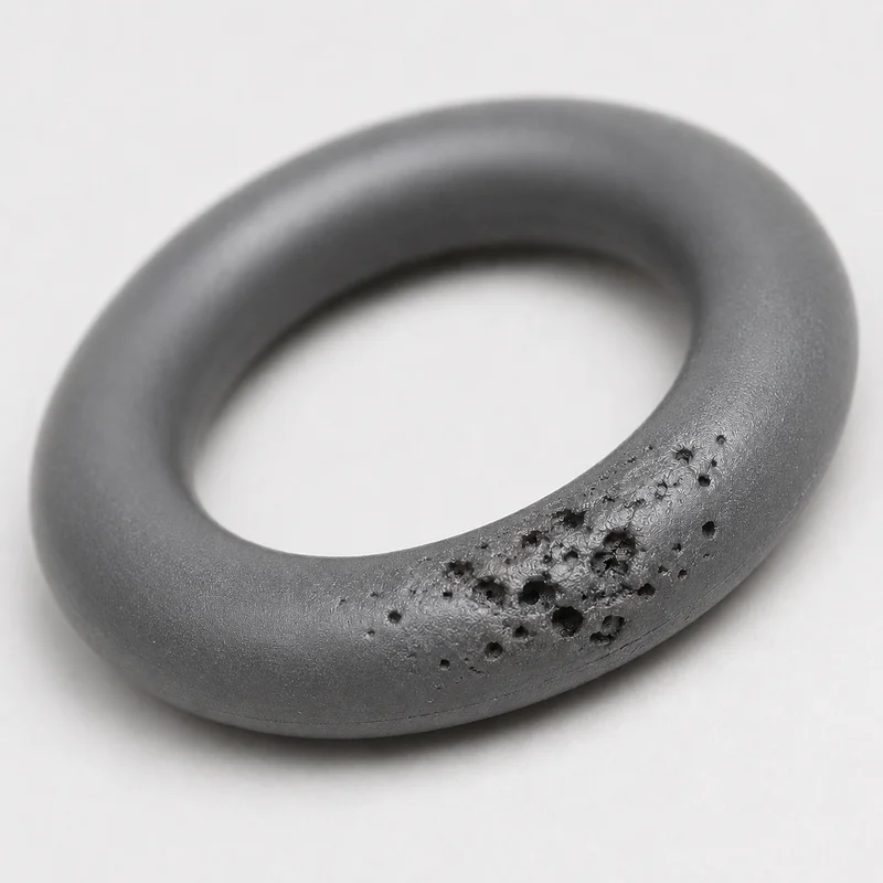
Shrinkage cavities occur where material is no longer fully replenished during the transition from a liquid or gas-rich state to a solid state. In casting processes, shrinkage cavities form when solidifying metal contracts faster than liquid material can feed into the affected area. In sintering processes, residual porosity remains because the powder particles cannot be fully compacted. In die casting and welding processes, gases become entrapped and can no longer escape during solidification.
The critical issue: Many shrinkage cavities are located just beneath the surface or only become exposed after machining. A component can appear flawless in its raw state and suddenly show visible cavities on the functional surface after turning, grinding or face milling. For sealing surfaces, bearing seats or bolted joints, even a shrinkage cavity measuring only a few tenths of a millimetre in diameter can be enough to compromise the function of the component.
For manufacturers, this means: Delivering components with shrinkage cavities means risking assembly defects, leaks, premature fatigue fractures and, in the worst case, product liability claims. Particularly in safety-critical components used in automotive supply, medical technology or hydraulics, 100% inspection is no longer optional, but a prerequisite for series approval.
For technical specialists:
Not all shrinkage cavities are the same. In practice, at least three basic forms are distinguished according to their formation mechanism: macro shrinkage cavities, meaning interconnected cavities caused by solidification shrinkage; micro shrinkage cavities, meaning finely distributed shrinkage porosity within the microstructure; and gas cavities, meaning round, smooth-walled voids caused by entrapped gases. With regard to their location, a further distinction is made between internal cavities, which are enclosed within the component; external or surface cavities, which are open to the cast surface; and exposed cavities, which are only revealed on a functional surface during machining. Each form has its own optical appearance: gas cavities appear regular and rounded with smooth walls, shrinkage cavities are irregular and branched with rough, often dendritic walls, while microporosities appear as a fine, dark texture. The evaluation strategy must be adapted accordingly; otherwise, harmless porosities may be incorrectly classified as defects.
Conventional methods for shrinkage cavity detection and their limitations
X-ray, CT, ultrasound, leak testing: Proven methods, but rarely suitable for series production.
Several non-destructive testing methods have become established for detecting shrinkage cavities. Each has its strengths and limitations once it has to be integrated into the cycle time of series production.
The common challenge: All four methods are designed for random sampling, laboratory use or targeted secondary inspection. For 100% inspection within production cycle time, with 50,000 to 100,000 parts per shift, they are either too slow, too complex or do not provide the information that is truly needed in series production: Where is the shrinkage cavity located, how large is it and is it actually relevant to the function?
X-ray inspection (radiography)
The classic method for non-destructive internal inspection. High-energy X-ray radiation penetrates the component and is attenuated to varying degrees by shrinkage cavities, pores or inclusions. A flat-panel detector captures the radiographic image, with shrinkage cavities appearing as dark areas. The method is considered a reference standard for aluminium castings, steel castings and weld seams.
Disadvantages in series production:
- Radiation protection required: shielded inspection cabinet, trained personnel, regulatory requirements
- Long exposure and evaluation times, often ranging from seconds to minutes per part
- Two-dimensional imaging of a three-dimensional component. Shrinkage cavities can be hidden behind load-bearing structures.
- High investment and operating costs
- In the case of ambiguous findings, subjective assessment by inspection personnel is required.
Did you know? The detection sensitivity of a radiographic image is typically around 1–2% of the wall thickness being penetrated. In a 20 mm thick casting, shrinkage cavities below approx. 0.2 mm can therefore no longer be reliably detected. Finer structures require either microfocus X-ray inspection or computed tomography, resulting in significantly longer inspection times.
Computed tomography (CT)
The further development of radiography. The component rotates in the beam path, and a three-dimensional volume image is reconstructed from hundreds of individual images. Shrinkage cavities, pores and inclusions can be precisely measured in terms of size, position and volume – an invaluable advantage for design validation and initial sample inspection.
Limitations of the method:
- Very long inspection times, ranging from several minutes to more than an hour per part, depending on the resolution
- High acquisition costs, usually only economically viable in an inspection laboratory.
- Limited component area per scan; large parts have to be scanned section by section
- Economically difficult to implement as a series production tool for 100% inspection in a production line.
Ultrasonic testing
A probe transmits high-frequency sound waves into the component. When they encounter interfaces such as shrinkage cavities or cracks, they are reflected. The position and size of internal defects can be calculated from the time-of-flight difference. This method is widely used for inspecting forged parts, rolled products and weld seams.
Limitations of the method:
- Couplant such as water, gel or oil is required between the probe and the component
- Sensitive to surface roughness, geometry and material structure
- Difficult to automate for complex geometries, often limited to point-by-point measurement
- Very small shrinkage cavities close to the surface are masked by the initial pulse
- Required cycle times are often not achievable
Leak testing
An indirect method: The component is pressurised with air, helium or a test fluid and inspected for leaks. Open, continuous shrinkage cavities are reliably detected in this way, making the method often indispensable for leak-tightness verification on cast housings, valves or hydraulic components.
Limitations of the method:
- Only through-going shrinkage cavities are detected; enclosed cavities remain invisible
- No information about the location, shape or size of the defect, only “leak-tight/not leak-tight”
- Component-specific sealing and fixtures are required
- Additional process step with separate cycle time
- No documentation of the defect pattern itself
Our approach: optical shrinkage cavity detection
From surface machining to documented inspection results: NELA’s optical shrinkage cavity detection makes critical material defects visible exactly where they are decisive for component quality, and transfers them into an automated, traceable inspection process.
-
Inspect machined functional surfaces
Optical shrinkage cavity detection focuses on machined functional surfaces. Turning, grinding or face milling can expose cavities on the surface. These visible shrinkage cavities change the reflection behaviour of the surface and are reliably detected by the camera and evaluation software.
-
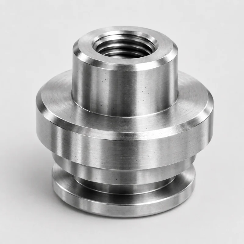
Automatically capture and evaluate surfaces
Illumination, sensor technology and the evaluation algorithm work together as a coordinated system. Face, outer cylindrical and internal surfaces are fully captured and automatically evaluated within the shortest possible time. Inspection is contact-free, without couplants, without radiation protection and without additional process steps.
-
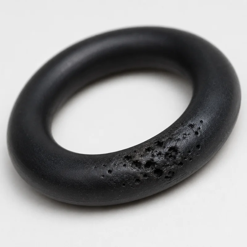
Document findings and safeguard quality
Every visible shrinkage cavity connected to the surface is detected, classified and logged with an image, timestamp and machine ID. This creates reproducible inspection results and a robust basis for quality assurance, audits, complaints and documentation requirements.
The physics behind shrinkage cavity inspection: light, shadow and topography
From an optical perspective, a shrinkage cavity is a local disturbance in reflection behaviour. On a smooth surface, light is reflected in a predictable way. As soon as a depression interrupts this pattern, which is exactly what an exposed shrinkage cavity does, the pattern of reflection and scattering changes. The key is to make this change visible enough for it to be detected reliably and reproducibly.
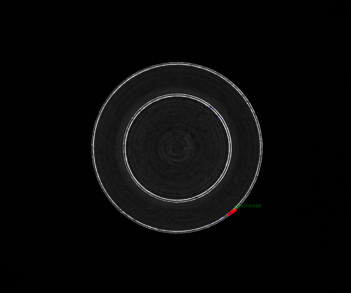
Dark-field illumination: shrinkage cavities in bright contrast
With dark-field illumination, light strikes the inspection surface at an extremely shallow, grazing angle. Based on the principle that the angle of incidence equals the angle of reflection, light from a smooth surface is largely reflected directionally past the camera. The image remains dark. However, when the light hits the edge of a shrinkage cavity, it is scattered towards the camera. The shrinkage cavity appears as a surface depression in bright contrast against a dark background. This makes the typical appearances of open shrinkage cavities highly detectable: sharp-edged shrinkage cavities and clearly defined gas cavities on sealing surfaces.
Shape-from-shading: depth instead of deception
Dark-field imaging shows that something is present at a given location. Shape-from-shading shows what exactly it is. In this method, the inspection object is illuminated sequentially from several precisely defined directions, and an image is captured for each illumination scenario. An algorithm uses the varying shadow gradients and brightness values to determine the surface normals for each pixel and derive a fine three-dimensional height relief of the surface. The method is particularly effective for local structures such as edges, craters and exposed shrinkage cavities; for the absolute global shape, directly height-measuring methods such as fringe projection or deflectometry can be used additionally if required.
This is crucial for optical shrinkage cavity inspection: A spot on the surface may be a shrinkage cavity or a harmless discoloration. Shape-from-shading provides the actual depth information and therefore the criterion needed to distinguish between a real cavity and a purely optical feature. Critical defects are clearly identified based on their actual depth, while harmless surface features are classified as non-critical.
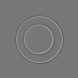
Dome illumination: detecting accompanying indicators
Discoloration, oxidation marks or smear spots often occur around shrinkage cavities and can be traced back to the casting or sintering process. Diffuse dome illumination eliminates directional reflections and makes these accompanying indicators clearly visible. This expands the diagnostic scope: Not only the shrinkage cavity itself, but also its formation context and therefore valuable information for root cause analysis and process optimization can be documented.
True shrinkage cavities vs. material-typical porosity
Particularly in sintered components, die castings or powder-metallurgical parts, a certain level of residual porosity is inherent to the material and permissible, or even desirable, within defined limits. Optical shrinkage cavity detection that reports every dark spot as a defect would flood the line with pseudo-rejects. The key is to reliably distinguish truly critical shrinkage cavities from acceptable porosity.
NELA solves this through a combination of spatial analysis, parameterizable thresholds and adaptive algorithms in the VisionCheck software. The evaluation examines parameters such as individual size, frequency distribution, cluster formation and position relative to the functional surface. Based on this, it determines whether a defect is critical to the component or not.
Did you know? In sintered parts, typical residual porosity in structural components such as gears, cams and flanges ranges from 1–8% by volume, corresponding to a relative density of 92–99%; self-lubricating plain bearings have an open porosity of 10–25% by design. In structural sintered parts, the individual pores are typically in the range of a few to several tens of micrometres and are evenly distributed throughout the microstructure. Critical shrinkage cavities, by contrast, usually occur as one or a few cavities with significantly larger dimensions and tend to accumulate in functionally sensitive areas such as bearing seats or sealing edges. Good image processing makes use of precisely these differences: It is not individual dark pixels that determine whether a part is accepted or rejected, but their spatial organisation.
When optical inspection is not enough: resonance testing as a partner
The best of both worlds.
Optical inspection has a physical limitation: It sees what is visible on the surface. Shrinkage cavities located deep inside the component, which are not exposed by subsequent machining, remain invisible even with optimal illumination. For applications in which both open and completely internal cavities need to be inspected, NELA combines optical inspection with resonance testing, also known as acoustic testing.
Resonance testing uses the component’s natural vibration behaviour. Each part has a characteristic frequency spectrum that depends on its geometry, material and internal structure. If this spectrum deviates from the reference spectrum of a flawless part, this is a reliable indicator of internal defects. The detection limit depends on the size, position and orientation of the defect: Cracks transverse to the direction of vibration propagation are the easiest to detect. Very fine cracks or individual pores far below the wavelength may remain undetected and must be assessed in advance through a feasibility study.
The advantage of integration: The component passes through the optical inspection station and resonance testing in a single cycle. No changeover, no separate line, no additional handling step. While optical inspection detects open shrinkage cavities on the functional surfaces, resonance testing expands the inspection spectrum to include hidden internal defects. Both results are merged in the NELA VisionCheck software and evaluated together for the pass/fail decision.
Automated shrinkage cavity detection in production with NELA
Up to 100,000 parts per hour. Zero compromises.
NELA systems are built for series production. On our glass table systems, face, outer cylindrical and internal surfaces of components are inspected in a single pass: fully automated, inline and in cycle time. Belt-based inspection systems are available for elongated or cylindrical components, while individual special-purpose solutions are developed for particularly challenging geometries.
Shrinkage cavity inspection is performed using the NELA TOPside and BOTTOMside sensors for face surfaces, OUTside for external cylindrical surfaces and INside for bores and internal surfaces, each with several parameterizable illumination levels. This enables shrinkage cavities in internal contours, on thread flanks or at the edges of through-holes to be detected.
Typical defects detected during shrinkage cavity inspection:
- Shrinkage cavities on face and sealing surfaces of cast and sintered components
- Gas pores and gas cavities on machined surfaces
- Micro shrinkage cavity clusters evaluated based on frequency distributions
- Surface shrinkage cavities in threads, bores and on edges
- Open cavities in weld seams and joining areas
- Accompanying indicators such as discoloration, oxidation and, in cast iron, microstructure-related graphite precipitations that can be visually mistaken for shrinkage cavities
Applications:
- Sintered components such as cams, gears, bushings, flanges, plain bearings and sintered magnets
- Cast components such as aluminium die castings, cast iron and steel castings
- Safety-critical automotive components such as brakes, steering systems and chassis components
- Hydraulic and pneumatic components, valve bodies and housings
- Medical technology components with high cleanliness and safety requirements
- Fasteners and formed parts with critical functional surfaces
Inspectable part sizes range from 1 mm to approx. 120 mm outer diameter, with repeatability starting from ± 1 µm. For sintered components, particularly gentle handling concepts can be used on request to ensure that the parts pass through the system reliably and without damage, even at high volumes.

The software behind it: NELA VisionCheck
Every inspection decision is automatically logged: with image, measured values, defect class, timestamp and machine ID. VisionCheck enables the creation of individual inspection programs and reduces pseudo-rejects through adaptive surface algorithms. This creates seamless quality documentation that stands up to audits and ensures traceability throughout the supply chain.
On request, NELA VisionCheck can be supplemented with a powerful AI module that makes your inspection even more efficient and flexible.
